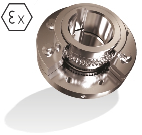
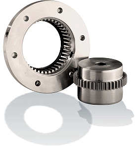
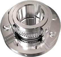
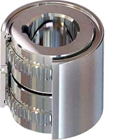
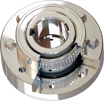
The new generation of the Gear Coupling. By incorporating the latest advances in Finite Element Analysis technology, Lovejoy has revolutionized the Gear Coupling. Increased nominal torque, larger maximum bore size and longer service life are just a few of the many advantages of the HercuFlex® coupling. Despite the advanced nature of these improvements, the HercuFlex® Gear Coupling still utilizes the standard AGMA flange interface to ensure field interchangeability.
Gear-couplings are the foremost coupling type. They can do things that many other coupling types are unable to perform, or that need expensive modifications and de-rating to function. Gear couplings have the highest power density, offer more variations, a wider size, torque, and bore capacity than any other coupling type. They are easily modified for shear pin service, floating shaft type, vertical applications, electrical isolation, limited end float, and can have a brake drum or disc added. While some features may be available on other couplings, it is typically easier and cost effective to modify a gear coupling. With all these advantages, the gear coupling is used on more applications versus the nearest competing coupling type.
The following is a list of the information necessary to assist in making a coupling selection.
Not all of these items will come into play in all selection processes.
These items include, but are not limited to:
» Application details.
» Type of motor and driven equipment.
» Motor horsepower or KW.
» Operating/coupling speed.
» Shaft sizes and separation.
» Space and size constraints.
» Environment (temperature, chemicals, etc).
» Balance requirements.
» Special modifications.
Refer to the gear coupling specifications charts displayed with each type of coupling throughout
this catalogue
. Visualization, specifications, and dimensional data for Lovejoy’s Hercuflex ® gear coupling products are all included.
Typically start with an
FX Type flanged gear coupling
or a
CX Type continuous sleeve gear coupling
and proceed from there.
Step 1: Review the gear coupling series and type as selected to ensure the selection meets application requirements.
Step 2: Determine the nominal application torque in in–lbs by using the following formula:
Application Torque:
( in–lb ) =
(HP x 63025) RPM
or Nm =
(KW x 9550) RPMStep 3: Review the Application Service Factor chart for the service factor number associated with the application where this coupling will be used. Multiply the application torque by the application service factor to determine the total torque required for the coupling selection.
Step 4: Compare the required total torque value with the nominal torque capacity listed in the Gear Coupling Selection chart for the desired coupling type.
Step 5: Check that the maximum bore size and the maximum RPM of the coupling type selected to ensure the coupling will meet these application requirements.
Step 6: Note any special requirements including the between shaft ends dimension for floating shaft and spacer types, shear pin torque, slide coupling details, mill motor tapered shaft data, and any other relevant information.
*Contact
jbj Techniques technical office telephone:
01737 767493
or
email:
info@jbj.co.uk
for any unusual applications or circumstances.
See
page 1 for application service factors.