Large stocks for quick delivery and in-house machine shop for exact fit to your application machinery.
Telephone:
+44 (0)1737 767493 or email:
info@jbj.co.uk

If the resilient bushes fail, metal-to-metal contact could occur, in order to minimise the risk of this situation, we recommend that the end user carry out periodic inspection of the coupling assembly with particular attention being applied to the resilient bushes. This can be further enhanced by the application of a large service factor to the coupling at the selection stage.
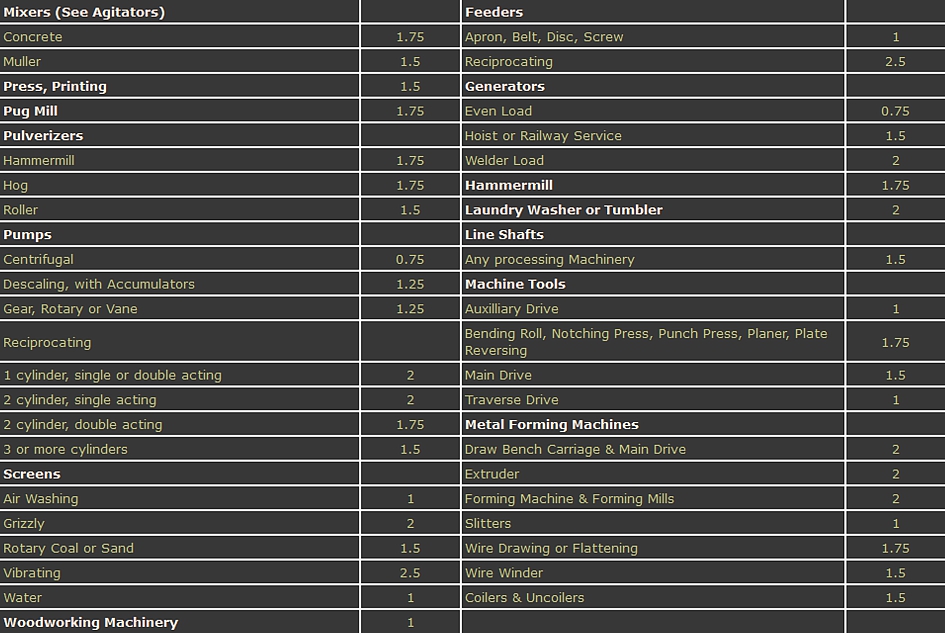
By the nature of the design of 'JXL' couplings, a large service factor is easy to achieve, as a general rule, a full compliment of resilient bushes with each coupling selection will naturally give a high service factor.
If the assembly is to be positioned in an inaccessible area where periodic inspection will be difficult to achieve or may be ‘overlooked’ a high service factor will be very desirable, in many cases the provision of a dia 50mm inspection hole in the bellhousing will save time when inspecting the coupling.
When selecting 'JXL' anti-static couplings for use inside bellhousings, consideration must be given to clearances between rotating and non-rotating parts, based on BSI 9-2000 EN50019: 2000-173, we recommend that this clearance be a minimum of 5.0 mm in all cases, however the standard this information is derived from advises that clearance shall be 1/100 of the maximum diameter (rotating component), but in no case shall the clearance be less than 1.0 mm, reference to this could be used in special circumstances, however it is envisaged that 5.0 mm should be possible in all cases.
'JXL' ATEX coupling hubs are machined with an additional grub screw at 90 degrees to the grub screw over the key slot, this is to provide additional security against the hubs creeping down one or other shaft when mounted vertically, we strongly recommend the use of this additional grub screw in vertical installations, however, if the additional grub screw is not to be used, it must be removed from the coupling hub and an alternate method sought, eg pinning of shaft keys, spacers or clamp design hubs.
In mining applications, it is not permitted to allow dust to enter equipment supplied, therefore any inspection holes in bellhousings must be fitted with solid covers.
'GGR' ATEX certificated bellhousings will be fitted with a centring to enable the pump to be removed without removal of the coupling hub from the pump shaft as standard, where the centring will not interfere with the pump fixing holes. In instances where the diameter of the centring would interfere with the pump fixing holes, provision of a removable pump face on the bellhousing may be required in order to assist with pump removal. This should be requested at time of quotation.

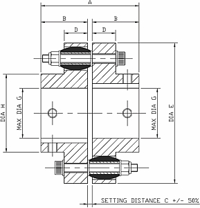
This guide is for the installation of ATEX compliant JXL couplings when a bellhousing is not used and covers the assembly of the coupling individual components.
Ensure each flange is clean. Fit each flange to their respective shafts. Line-up coupling flanges by checking dimensions between flange faces at 90° intervals and by using a straight edge across the outside diameter of flanges at 90° intervals.
If possible a dial test indicator may be used to give accurate details of alignment. The flanges should be aligned to within the following tolerances noting that where one misalignment is present then the others must be reduced proportionally. Careful alignment will extend coupling life.

All couplings, plus or minus 0.375° per hub maximum, 0.75° total.
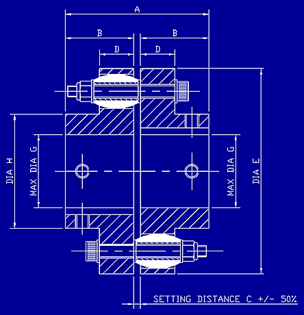
All couplings, plus or minus 50% of flange gap (dimension 'C' below in drawing)
When the coupling hubs are within the correct alignment fit the coupling pins, liners and resilient elements ensuring that each pin assembly has three washers fitted; one under the cap screw head and one at either end of the element. The pins should be fitted with the self locking nut adjacent to the resilient element. Where half or less number of pin assemblies are being used, all elements should be fitted into one flange. When all pin assemblies are fitted tighten the self locking nuts in pairs at 180° to each other to the correct torque.
Periodically check flange alignment and resilient elements for wear.
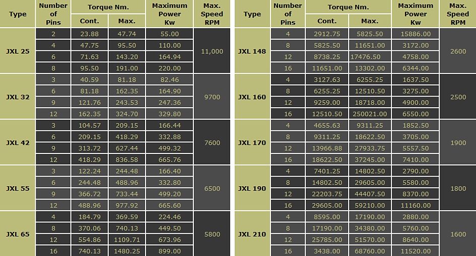
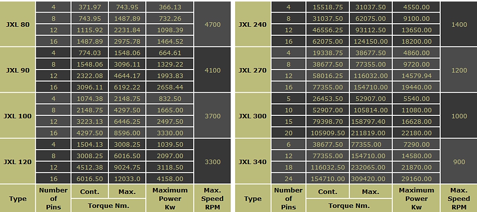
Note: 'JXL' couplings are capable of accepting a momentary overload of twice nominal torque and have an operating temperature range of -50°C to +105°C.
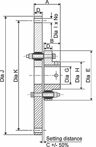
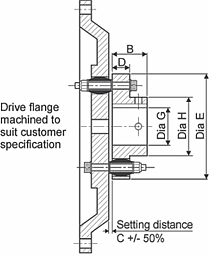
This guide is for the installation of JXL couplings when a bellhousing is used.
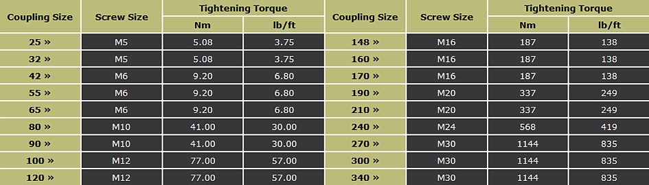
Coupling pins are tightened to the correct torque prior to leaving our premises; these values should be re-checked prior to installation. Under no circumstances should the couplings be assembled with the pins tightened to any torque other than the specified values.
Fit the relevant coupling hub onto the motor shaft. As a general rule the face of the coupling flange will be flush with the end of the motor shaft with any necessary offset being applied to the hub fitted to the pump shaft. In any case the correct setting distance must be maintained, tighten grub screw(s) and re-check the setting distance.
Fit the pump centring to the pump (when supplied) then fit the relevant coupling hub to the pump shaft, position the hub suitably to obtain the correct setting distance, tighten grub screw(s) or clamp screw(s) if the pump has a spline shaft, and re-check the setting distance. When the coupling assembly is to be mounted in a vertical position, we strongly recommend the use of the additional grub screw positioned at 90° to the key slot, to reduce the risk of the coupling hubs creeping down the shafts.
If the additional grub screw is not to be used it must be removed from the coupling hub.
Assemble the pump and motor to the bell housing ensuring that there is no loose matter i.e. grub screws washers etc remaining inside the housing and that no rotating component is within 5.0 mm of any non rotating part.
Tighten all bolts to the correct torque values. We recommend the use of shake proof washers with all bolts.
All couplings, plus or minus 50% of flange gap (dimension 'C' below in drawing).
Periodically check flange alignment and resilient elements for wear.
Note: 'JXL' couplings are capable of accepting a momentary overload of twice nominal torque and have an operating temperature range of -50°C to +105°C.