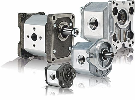
A complete range of reversible units and hydraulic gear motors compliment the range of hydraulic motors and pumps for all types of industrial process, heavy plant, agricultural and commercial equipment.
These are some of the criteria to consider when deciding which size gear motor is needed for an application.
Fluid velocity:
Calculate the velocity (v) of a fluid in a pipe as follows:
v = Q
÷ (6 • A [m/s])
Q = flow rate [litre/min]
A = inside area of pipe [cm²]
Absorbed flow rate:
Calculate flow rate (Q) as follows:
Q = (V • n • 10 -3)
÷ hvol [litre/min]
V = displacement [cm³/rotation].
n = rotation speed [rotations per minute].
hvol = motor volumetric efficiency (take 0.95 as an indicative value for rotation speeds ranging between 1000 and 2000 rotations per minute).
Delivered torque:
Calculate necessary torque (M) of a motor subject to pressure differential between input and output as follows:
M = (V •
Dp •
hhm)
÷ 62,8 [Nm]
V = displacement [cm³/rotation].
Dp = pressure differential [bar].
hhm = hydromechanical efficiency (take 0.80 as indicative value under cold conditions and 0.85 under working conditions).
Delivered power:
Calculate hydraulic power (P), delivered by a motor subject to a pressure differential between input and output as follows:
P = (Q •
Dp •
htot)
÷ 600 [kW]
Q = flow rate [litre/min.].
Dp = pressure differential [bar].
htot = total motor efficiency (
hhm • hvol).
Values for
hvol and
hhm (and consequently
htot) depend on pressure differential between supply and delivery, rotation speed, fluid features (temperature and viscosity) and filtering degree.Contact jbj Techniques technical office, email: info@jbj.co.uk or telephone: +44 (0)1737 767493 for further details on efficiency. The proper values for flow rate, torque and supplied according to pressure differential, rotation speed and set test conditions, can be found via this link for the
Performance Curve pages.
How to select the correct size Hydraulic Gear Motor . . .
There are several factors that need to be known before a calculation can be used to decide the most suitable sized hydraulic gear motor for an application.
1) First of all find out if the required output torque from the hydraulic gear motor is starting torque or running torque. Not that either will effect the way you size the hydraulic gear motor, but it is worth remembering that starting torque is, in most instances, higher than running torque.
2) Required output speed from the hydraulic gear motor.
3) Available hydraulic oil pressure of the application hydraulic circuit.
4) Required output shaft, required mounting interface and required inlet and outlet porting, flanged or threaded.
5) Don’t forget the
coupling from the hydraulic motor shaft to the driven shaft. jbj Techniques have a wide range of
mechanical power transmission couplings to suit many applications. We would be happy to help.
Example calculation:
An application requires an output torque of 50 Nm at a speed of 2000 rpm and the hydraulic oil pressure available is 150 bar.
Using formula: Vm = (20 x p x T) ÷ DP
Vm = Hydraulic gear motor displacement in cc/rev.
T = Required output torque 50Nm.
ΔP = 150 bar.
Put the above information into the formula:
Vm = (20 x 3.142 x 50) ÷ 150
Vm = 20.94 cc/rev.
The above figure gives you the theoretical required hydraulic motor displacement to meet the above requirements. However it does not take into account the hydraulic motors mechanical inefficiencies.
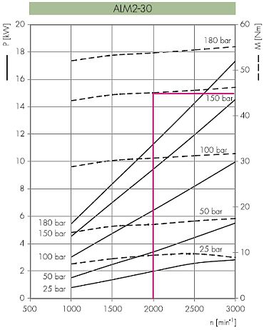
The nearest hydraulic motor to the above Vm displacement figure of 20.94 cc/rev would be the Marzocchi group 2 ALM2 size 30. This has a displacement of 21.1 cc/rev. Looking at the performance charts below for the size 30, the dotted lines, and the 2000 rpm line. Taking the vertical 2000 rpm line until it intersects the 150 bar dotted line, and then taking a straight horizontal line at the intersection point to the torque output figures on the right of the graph you will see that the actual output torque of the motor will be 45 Nm. Therefore this motor will not meet the requirements.
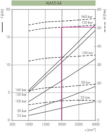
If we then look at the next size motor up the ALM2-34, this has a displacement of 23.7 cc/rev. Then looking at the performance chart for this size of motor, and carrying out the same procedure as we did for the ALM2-30 it can be seen that this motor will produce just over 50 Nm. This would then be the hydraulic gear motor most suitable for the job without unnecessarily over sizing the motor.
Overall physical size can often be an important consideration. Available flow to the gear motor from the system can determine whether a small motor at high pressure is used or a larger motor at low pressure. A larger motor at lower pressure will achieve longer life but a lack of space available may determine that a smaller motor is used.
Controlling the speed of the gear motor is another requirement depending on the application. Please contact jbj Techniques technical office for further details and help to choose the correct size gear motor for your application, email:
info@jbj.co.uk or telephone:
+44 (0)1737 767493These performance charts above plus dimensions, flange, shaft and port details, ordering codes, installation and maintenance details can be found for the range of Marzocchi gear motors within these two technical specification catalogue links:
www.jbj.co.uk/e-publications/ALM-series-gear-motors-from-jbj-Techniques-Limited/index.html
and
www.jbj.co.uk/e-publications/GHM-series-gear-motors-from-jbj-Techniques-Limited/index.html
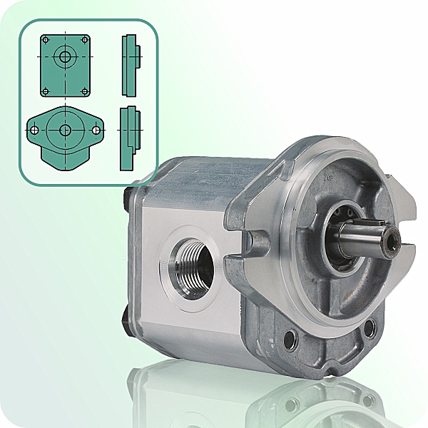
ALM 1 series: Aluminium bodied, aluminium flanged, hydraulic gear motors with displacement from 2.8 to 11.0 cm³/rev. max. speed 2,200 to 5,000 rpm, flow at 1500 rev/min 3.9 to 15.7 litres/min, depending on model.
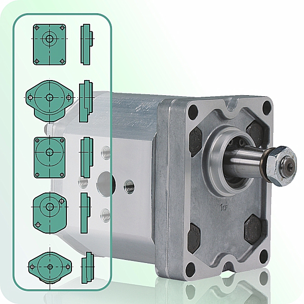
ALM 2 series: Aluminium bodied, aluminium flanged, hydraulic gear motors with displacement from 4.5 to 28.2 cm³/rev. max. speed 2,500 to 4,000 rpm, flow at 1500 rev/min 6.4 to 40.1 litres/min, depending on model.
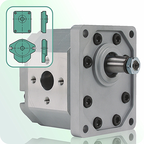
ALM 3 series: Aluminium bodied, aluminium flanged, hydraulic gear motors with displacement from 22 to 87 cm³/rev. max. speed 2,000 to 3,500 rpm, flow at 1500 rev/min 31 to 124 litres/min, depending on model.
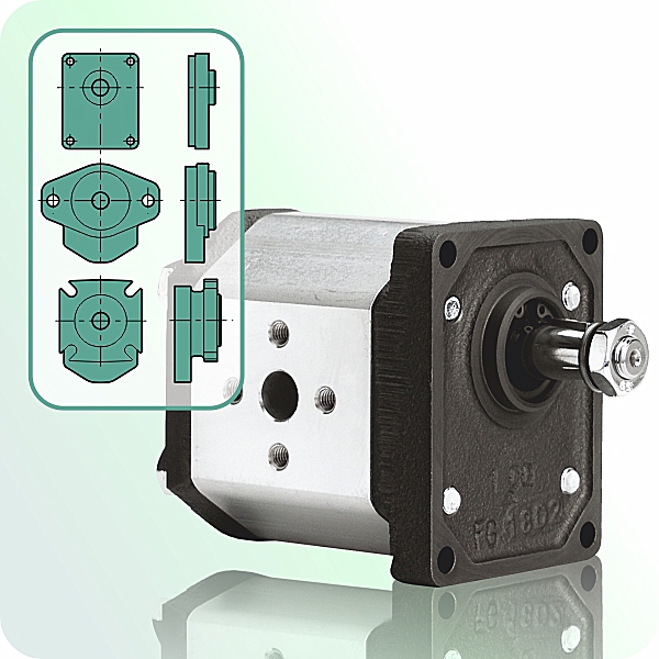
GHM 1 series: Aluminium bodied, cast iron flanged, hydraulic gear motors with displacement from 2.8 to 11.0 cm³/rev. max. speed 2,200 to 5,000 rpm, flow at 1500 rev/min 3.9 to 15.7 litres/min, depending on model.
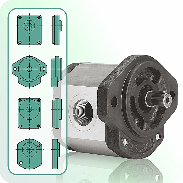
GHM 2 series: Aluminium bodied, cast iron flanged, hydraulic gear motors with displacement from 4.5 to 28.2 cm³/rev. max. speed 2,500 to 4,000 rpm, flow at 1500 rev/min 6.4 to 40.1 litres/min, depending on model.
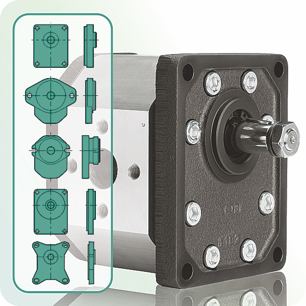
GHM 3 series: Aluminium bodied, cast iron flanged, hydraulic gear motors with displacement from 22 to 87 cm³/rev. max. speed 2,000 to 3,500 rpm, flow at 1500 rev/min 31 to 124 litres/min, depending on model.
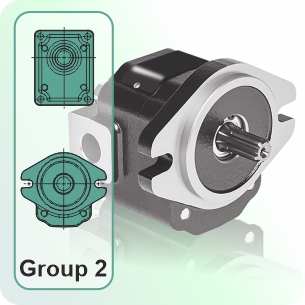
FCIM2 series: cast iron bodied, cast iron flanged,
hydraulic gear motors with displacement from 4.5 to 31 cc/rev. maximum speed 3,500 rpm.
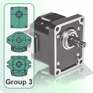
FCIM3 series: cast iron bodied, cast iron flanged, hydraulic gear motors with displacement from 21.5 to 88 cc/rev. maximum speed 3,000 rpm.
Elika® low noise, high efficiency, gear motors - the latest edition to the Elika range . . .
Marzocchi Elika
® gear motors are built on patented
ELIKA® Gear Technology, which reduces noise levels by an average of 15 dBA compared to conventional external gear pumps and motors. The use of helical gears ensures smooth, continuous motion even with a reduced number of teeth. This lower tooth count in the helical format shifts the pump’s fundamental noise frequencies, resulting in a quieter and more pleasant sound profile.
The distinctive Elika
® Profile, patented by Marzocchi Pompe, eliminates the encapsulation phenomenon common in standard gear pumps, removing one of the primary sources of noise and vibration.
By minimizing pressure oscillations and vibration transmission to surrounding components, Elika technology significantly lowers the overall noise of the hydraulic system. Additionally, specially designed compensation zones in the flange and cover, insulated by anti-extrusion reinforced gaskets, enable free axial and radial movement of the bushings, further enhancing performance and durability.
Low noise, low pulsation, high efficiency gear motors that use fluid power from the hydraulic system of a machine to create rotary mechanical power.
Link to technical specification catalogue for the »
Elika® helical gear motors
A range of mounting flanges, output shafts, and ports are available to suit a variety of applications.
We trust that this is of help but feel free to contact the jbj Techniques technical office,
email:
info@jbj.co.uk or telephone:
+44 (0)1737 767493 if you need assistance or have further questions.
Selecting a Hydraulic Gear Motor That Fits the Application
A practical guide to matching torque, speed, flow and pressure with real working conditions.
Gear pumps and gear motors perform opposite functions
A hydraulic gear pump takes mechanical energy from an engine or electric motor and converts it into hydraulic flow and pressure. A hydraulic gear motor reverses the process, using hydraulic flow and pressure to produce mechanical torque and rotation.That makes gear motors a compact and practical means of driving auxiliary machinery wherever a hydraulic power supply is already available.They can be used on industrial machinery, agricultural equipment, heavy plant, marine vessels, commercial vehicles and many other mobile or industrial applications. However, selecting the correct motor requires more than matching a shaft size and mounting flange.
Start with the work the motor must perform
The first questions should be:
» What power will the driven equipment require?
» What running torque is required?
» What starting torque must the motor provide?
» At what speed must the driven equipment operate?
» Will the motor run continuously or intermittently?
» Must it operate in both directions?
» Will it experience shock loads or external axial/radial shaft loads?
» What will the operating temperature be?
» Hydraulic fluid the motor will run on?
These application requirements define the mechanical output expected from the motor.
Then consider the available hydraulic supply
Motor displacement, hydraulic flow and pressure differential work together to determine output speed and torque.
In simplified terms:
» Available oil flow determines motor speed.
» Pressure differential determines available torque.
» Motor displacement influences both.
A smaller-displacement motor may provide the required speed but need a higher operating pressure to deliver the necessary torque. A larger motor can produce the same torque at a lower pressure, which may contribute to longer working life, although its greater physical size may not suit the available and it may have a reduced speed limit.
Selection is therefore a balance between performance, available hydraulic power, installation space and expected operating life.
Theoretical figures are only the beginning
Theoretical primary calculations provide a useful starting point, but an actual motor will be affected by volumetric and mechanical losses. Oil viscosity, operating temperature, cold-start conditions, driven equipment inertia filtration and speed all influence real-world performance.
For this reason, calculated displacement should be checked against the manufacturer’ performance data before the final motor is selected. Engineers wishing to examine the calculations in greater detail can read our hydraulic gear motor sizing guide.
The complete specification should also consider:
» Oil type and viscosity.
» Minimum and maximum operating temperatures.
» Available system pressure.
» Available system flow.
» Required direction of rotation.
» Mounting flange.
» Output shaft.
» Inlet, outlet and drain connections, (external or internal drain).
» Method of coupling to the driven equipment.
» External radial or axial shaft loads.
» Noise level.
A gear motor as part of a complete drive system
In one jbj Techniques project, hydraulic power already available on a road-marking vehicle was used to operate a gear motor. The motor provided the mechanical drive for a triple gear pump assembly, with three different pump displacements supplying three separate machine functions close to the required operating area. Note that selecting the motor also required consideration of the combined pump loads, their operating sequence and any simultaneous demand.
The arrangement demonstrates that a gear motor need not be considered as an isolated component. It can become the link between an existing hydraulic system and an additional mechanical or hydraulic requirement. By using this system the customer deleted the need for long multiple hose runs from three separate pumps from the front to the rear of his machine.
Hydraulic gear motors from jbj Techniques
jbj Techniques supplies a range of hydraulic gear motors with a choice of displacements, mounting flanges, output shafts and port arrangements, including cast-iron models developed for demanding applications requiring high pressure capability, durability and reliable performance.
More importantly, our engineers are able to consider the motor as part of the complete driveline, including its hydraulic supply,
mounting arrangement,
coupling and driven equipment.
Because the correct gear motor is not simply one that fits the available space. It must produce the required torque and speed, operate within the available flow and pressure, and remain reliable under the actual working conditions.
Link to:
How to select the correct size Hydraulic Gear MotorIf you are selecting a hydraulic gear motor, or need to integrate one with the available hydraulic supply, mounting arrangement and driven equipment, jbj Techniques can assess the complete application.
For help selecting a hydraulic gear motor and the associated drive components, contact jbj Techniques:
Telephone:
+44 (0)1737 767493Email:
info@jbj.co.uk
#DriveLineHarmony