Expand existing hydraulic pressure range with minimum effort, minimum cost, maximum effect!
Pressure intensification at its best.

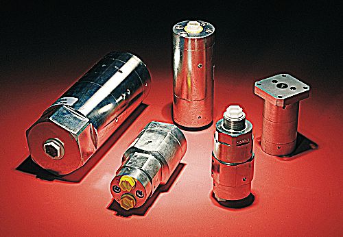
» Hydraulic Workholding on Machine Tools.
» Hydraulic Power Packs.
» Subsea R.O.V.’s.
» Press Applications.
» Pressure Die Casting Machines.
» Static and Impulse Testing Equipment.
» Stone Crushing Machines.
» Hydraulic Construction Tools.
» Demolition Tools.
» Quick Die Changing Equipment.
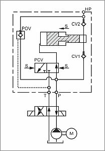
These pressure intensifiers are based on a piston principle, where a larger diameter piston pushes a smaller diameter piston, thus increasing the pressure to a factor equal to the ratio: Larger diameter area divided by smaller diameter area. The outlet pressure will always be proportionate to the supplied pressure.
Pilot operated check valves can be built in to allow high pressure side to be relieved through the intensifier.
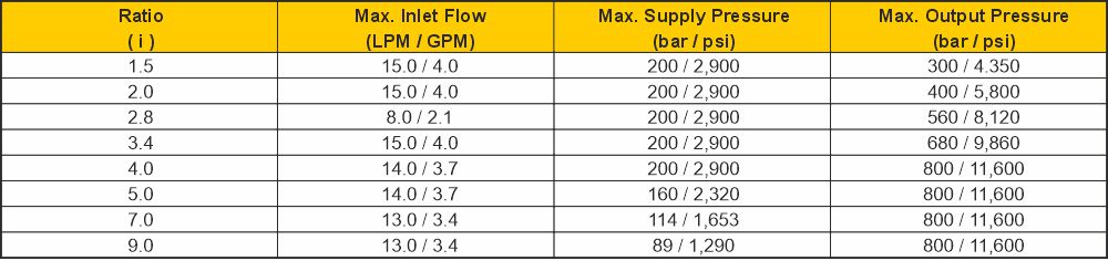
The supplied flow and pressure to the MP-T are dependent on the intensification ratio chosen.
The table shows the flow and pressure for each model. Flow Q1 is when the pump pressure has been reached, and flow Q2 is moving up the vertical part of the curve (see graph left).
Please note flow values will vary with the viscosity of the fluid. Inlet values must not be exceeded.
Filtration of hydraulic media is essential due to the precise tolerances built into each quality unit.
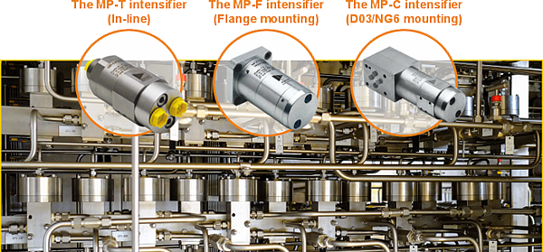
Compact hydraulic pressure intensifiers offer an easy, energy-saving, safe and cost-efficient solution to achieving a higher output pressure from an existing low-pressure power source. Low pressure supplied to the inlet port eg: 15 - 200 bar / 218 - 2,900 psi ~ is transformed to a higher pressure at the outlet port ~ from 20 - 4,000 bar / 290 - 58,000 psi. ScanWill’s pressure intensifiers are offered in cast iron and steel, with a chrome finish, as well as in stainless steel for the oil & gas sector.
The MP Series Hydraulic Pressure Intensifiers Increasing the Pressure in Production Lines
In large systems there can be problems maintaining the pressure for all functions, or a higher pressure is required for one function. Hydraulic pressure intensifiers can be inserted where needed ensuring sufficient pressure for all functions.
A hydraulic system is sometimes designed around its most demanding function.
If one operation requires substantially higher pressure thaneverything else, the apparent solution is to design the complete system to operate at that pressure. That may be necessary in some applications, but not in every application.
Where high pressure is required only at a particular point or during one part of the operating cycle, a hydraulic pressure intensifier may provide a more efficient alternative.
A hydraulic pressure intensifier, sometimes referred to as a hydraulic booster, uses the existing hydraulic supply to produce a higher pressure at its outlet.
This allows the main system to continue operating at a lower pressure while the intensifier supplies a separate high-pressure function locally and on demand.
Applications might include:
» Clamping.
» Pressing.
» Punching.
» Forming.
» Cutting.
» Testing.
» Workholding.
» Other intermittent high-pressure operations.
The important distinction is that the complete hydraulic system does not necessarily have to be designed around the pressure required by one function.
The pressure intensifiers supplied by jbj Techniques can incorporate a low-pressure bypass. Where an application initially requires high flow at a lower pressure, the intensifier allows the system flow to pass through directly. This can provide rapid movement or fast approach before the higher-pressure operation begins.
When greater pressure is required, for example during final clamping, pressing or cutting, the intensifier automatically begins operating.
This can shorten the overall operating cycle while limiting active pressure intensification to the part of the cycle in which it is needed.
Pressure may remain trapped within the intensified circuit after operation. Suitable isolation, pressure relief and controlled depressurisation must therefore still form part of the system design.
A pressure intensifier does not produce additional energy. It exchanges flow for pressure.
Its operation is based upon the relationship between force, pressure and piston area. A larger hydraulic piston driven by the low-pressure supply acts upon a smaller high-pressure piston. The difference in piston areas determines the theoretical pressure ratio.
As output pressure increases, the available high-pressure flow is correspondingly lower than the inlet flow. Efficiency losses must also be allowed for when calculating actual performance.
Pressure intensification is therefore particularly suited to applications requiring a relatively small volume of oil at high pressure. It is less likely to be appropriate where continuous high pressure and high flow are required simultaneously.
Designing the entire system for its highest pressure requirement can affect considerably more than the pump.
Valves, hoses, pipework, filters, seals, fittings and other components may all need to be selected for the higher working pressure. This can increase the size, complexity and cost of the installation.
Operating the complete circuit at higher pressure may also increase energy consumption, heat generation, leakage and component loading.
By maintaining a lower main system pressure and intensifying it only where required, it may be possible to:
» Reduce the required size or pressure rating of the main hydraulic power unit.
» Lower energy consumption during less demanding operations.
» Reduce unnecessary heat generation.
» Limit high-pressure loading on the remainder of the circuit.
» Use smaller or less costly components outside the intensified section.
» Produce a more compact installation.
» Reduce the overall cost of ownership.
These benefits depend upon the application. A pressure intensifier should not be treated as an automatic substitute for a correctly sized high-pressure power unit.
There is also an important safety consideration.
Hydraulic systems contain stored energy, and fluid released under pressure can cause severe injury. The risks become still more serious at very high pressures.
In suitable applications, local pressure intensification can reduce the proportion of the hydraulic circuit exposed to very high pressure.
This may reduce the number of components requiring the highest pressure ratings and confine the associated risks to a smaller, clearly defined section of the system.
This does not remove the high-pressure hazard.
Every component within the intensified section must be suitable for the maximum pressure it could experience. The design must also consider pressure relief, isolation, guarding, controlled depressurisation and the possibility of pressure remaining trapped after the main hydraulic supply has been switched off.
Installation, inspection and maintenance procedures must reflect the pressures involved. Leakage should never be investigated by hand, and work must not begin until stored hydraulic pressure has been safely released.
Reducing the extent of the high-pressure circuit can assist safe system design, but it does not reduce the need to treat that section with appropriate care.
Correct selection requires more than comparing the available inlet pressure with the desired outlet pressure.
The following should be established:
» Available inlet pressure and flow.
» Required outlet pressure.
» Required volume and flow at high pressure.
» Frequency and duration of operation.
» Duty cycle.
» Permitted pressure build-up time.
» Hydraulic fluid and operating temperature.
» Space and installation constraints.
» Acceptable pressure losses.
» Required pressure controls and relief arrangements.
» How the intensified section will be isolated and depressurised safely.
The behaviour of the driven equipment must also beunderstood. A clamping application requiring a small volume of oil to reach and maintain pressure presents a very different duty from an actuator expected to move continuously at high pressure.
A pressure intensifier can be a compact and effective way of adding a high-pressure function to an otherwise lower-pressure hydraulic system.
Its value, however, does not come simply from producing a larger pressure figure. The real benefit lies in understanding where high pressure is required, how much high-pressure flow is needed and whether the remainder of the circuit genuinely needs to share the same pressure rating.
In the right application, local pressure intensification may improve efficiency, reduce system size and cost, and limit the extent of the very-high-pressure zone.
In the wrong application, it may add complexity without delivering a worthwhile advantage.
jbj Techniques can supply hydraulic pressure intensifiers and assist with evaluating their suitability as part of the wider hydraulic system.
Sometimes the answer is not to make the entire system work at a higher pressure, but to apply higher pressure only where it is required.