Splitter Gearboxes / Multiple power take-off units
jbj Techniques 'AM' splitter gearboxes (or multiple PTOs) are available in a number of mounting formats with various increasing and decreasing ratios.
Choice of pump drive output configuration, number of outputs, installation orientation and output location.

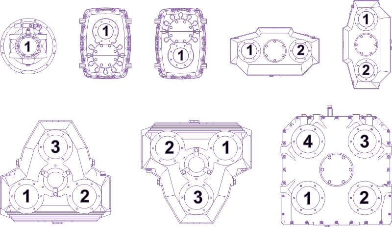
The multiple pump drive range of equipment allows a single or a multiple of pumps to be driven from a single prime mover.
Single pump drives allow a pump to be close coupled to a diesel engine that has a flywheel and flywheel housing in accordance with SAE standards (non standard can also be accommodated). Supplied in a kit format consisting of a bellhousing fully machined to suit the particular pump mounting and a flexible coupling to suit the engine flywheel and particular pump shaft.
Multiple pump drives allow two or more pumps to be driven from a single prime mover. OR . . . not only a mechanical power splitter but how about using these as dual drive inputs? Not splitting the power from the prime mover through to multiple outputs such as gear pumps, screw pumps, vane pumps, etc. but transmitting power from multiple prime movers to a single driven output, pump, mechanical power drive train? »
LINK to diagram.
Available in a number of mounting formats, sizes and increasing and decreasing speed ratios.
All models may be close coupled directly to the prime mover (Model B) or may be fitted with an over-centre clutch (except AM 365 and AM 480) for close coupling (model BD) or for independent mounting (model BDS).
The multiple pump drive units are constructed from:-
» cast iron casings.
» straight tooth gears case hardened and ground, shaved on AM216, AM320, AM220, AM330 series.
» ball bearings.
» case hardened shafts.
» Viton seals on input shafts.
The input shaft is splined to the primary drive gear which transmits the drive to the secondary gear on whose axis drives the pump. The direction of rotation is therefore opposite from input to output.
TECHNICAL DATA
Ratio - Represents the ratio between the input speed (prime mover) and output speed (pumps).
Ratios lower than one indicate the unit acting as a speed increaser and higher than one acting as a speed reducer.
Note the output ratio is identical on all outputs ports of the same unit.
Maximum input torque M1 (Nm) - Is the maximum torque which can be transmitted by the input shaft to give a theoretical gear life (L10) of at least 5,000 hours.
For units that are fitted with a clutch or a coupling the maximum input torque may be limited by the torque capacity of the clutch or coupling.
Each output maximum torque M2 (Nm) - Is the maximum torque that can be transmitted by each output port.
Maximum speed N1 (RPM) - Is the maximum speed of the input shaft.
Moment of inertia J (Kg/m²) - Is referred to the input shaft and is calculated in accordance with ISO standards.
SELECTION
The fundamental elements on the selection of a pump drive are:-
1) The number and type of pumps. Depending on the overall dimensions of the pumps and associated pipework it is possible to establish the maximum centre distances required.
2) Maximum torque requirement of each pump output. Verify that the maximum torque requirement is below the maximum value for each chosen pump or combination of pumps.
3) Maximum input torque. Verify that the maximum input torque is below the maximum indicated value for the particular model. In the case of a pump drive fitted with an over-centre clutch (models BD and BDS) it is important that the input torque is at least 20% below the maximum transmittable for that particular clutch.
4) Maximum input speed. Verify that the maximum input speed is below the maximum value indicated for that particular model. Check that the pump direction of rotation is opposite to that of the prime mover.
5) Service factor. A suitable safety factor should be applied to ensure the Integrity of the drive.
COOLING
With reference to the Maximum Permissible Input Power table on page 12 of this catalogue link in conjunction with the anticipated duty cycle and unit operating ambient temperatures will indicate whether a cooling system will be required.
If in doubt contact jbj techniques Technical Department, telephone: 01737 767493 or email: info@jbj.co.uk
It is always advisable to check the actual pump drives oil temperature during the first few working hours to ensure that the oil temperature does not exceed 105°C for synthetic oil, 80°C for mineral oil.
For types AM 220, 230, 232, 330, 345, 365 and 450 a cooling system is readily available. This comprises of an oil circulation pump that is driven from the pump side of the input shaft together with either a water/oil or an air/oil heat exchanger. Such a system allows for a higher continuous working power to be used.
DIESEL ENGINE CONNECTION
For diesel engine driven applications the pump drives can be supplied complete with all adaption kits for close coupling to engines that have flywheel and flywheel housings conforming to SAE standards. See dimensioned table on page 12 (link) for relevant data. Non SAE standard flywheels and flywheel housings may also be accommodated.
In the case of an application incorporating a clutch, the clutch pilot bearing is not an inclusive part of the clutch and has to be specified separately.
INSTALLATION
Great care has to be taken in the mounting of the assembled unit. Please refer to page 7 of this Pump Drives catalogue link for application examples.
LUBRICATION
The pump drives are supplied without oil. Before use the units must be filled with the appropriate grade of oil up to the full mark on the dipstick. The oil capacities shown in the catalogue are approximate quantities only. It is recommended that a gear oil with a minimum viscosity of 95 and an EP additive be used.
Some suitable oils for use in specific ambient temperatures are shown in the table on page 13 of this catalogue link.
The oil must be changed after the first 50 hours of work and subsequently every 1,000 hours or every 12 months whichever is the sooner thereafter.
The oil level should be periodically checked and topped up if required.
Dual drive application idea.
Transmit power from multiple prime movers to a single driven output, pump, mechanical power drive train? Not just splitting power but apply mechanical power from different sources to the same output. An AM220 splitter gearbox / multiple pump drive PTO connected to two hydraulic clutches in order that mechanical power can be transmitted from more than on prime mover.